What is Software Architecure
This article explains software architecture by analysing real architecture diagrams. The diagrams are from a google images search.
Google is a good place to start exploring a subject. So I did a search on the topic Software Architecture . Because I didn't want to read to much definitions I switched to the image search. You can see the result of the search in figure 1 .

Figure1:
Please do the search yourself and browse trough several pages. You will see lots of diagrams showing boxes and lines. So a software architect is somebody who draws boxes and lines. Looks like Visio or PowerPoint are the tools for a software architect.
The Boxes
The boxes and the lines are symbols for the building blocks in software architecture. A system can be divided into several subsystems that are represented by boxes.

Figure2:
Source: http://msdn.microsoft.com/en-us/library/bb190164.aspx
There are many names for subsystems. Depending on the fad of the day it is important for an architect to use the proper name to distinguish his system from prior technologies.
| Name | Technology |
|---|---|
| Module, subroutine | Basic |
| Component | Component models e.g. EJB |
| Class, package | Object orientation |
| Service | Service oriented architecture |
The Lines
Two boxes can communicate with each other if they are connected by a line. A double sided arrow is not directed and the communication can be therefore initiated from both ends. If it is not a simple line but an arrow the communication can only be initiated in one direction towards the arrowhead. An arrow also documents a dependency the component from ...
In figure 3 you can see a UML diagram with different types of lines and arrows.
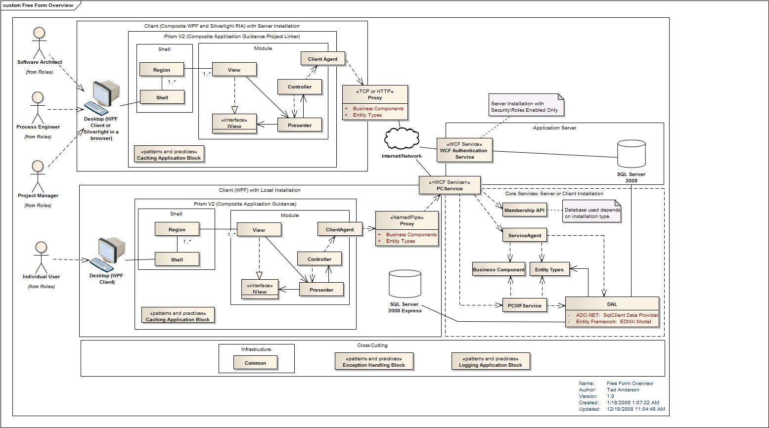
Figure3:
Source: http://realworldsa.blogspot.com/2009/06/prism-composite-wpf-and-silverlight.html
There are also different names for the lines:
| Name | Technology |
|---|---|
| Connector, Adaptor | EAI, Middleware |
| Interface | OO, SOA |
The lines are missing in some diagrams as shown in figure 4 . Components in those diagrams can communicate with neighboring components or with the next component further down.
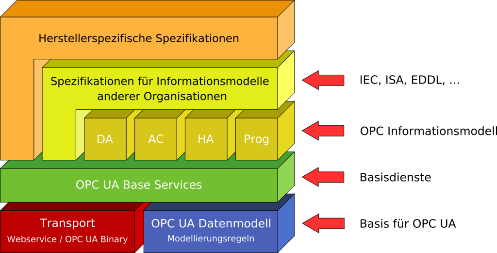
Figure4:
Source: http://de.academic.ru/dic.nsf/dewiki/1036788
Layers of Abstractions
There are more architectural elements than boxes and lines. In figure 5 the diagram is structured into three layers by dotted lines. Each layer is an abstraction of functionality. The layer on the bottom offers data management functionality to the services layer. And the services layer offers functionality to several clients on the Internet. Each layer is build onto the functionality of the next layer down the stack.
Figure5:
Source: http://geoinfo.sdsu.edu/reason/task.htm
Infrastructure Components and Services
Figure 6 displays a multi-tier architecture like the ones we have already seen. But to the left and to the right we have vertically aligned boxes that extend over all layers. These vertical boxes are represent cross cutting concerns like infrastructure services that can be used in every component of the system.

Figure6:
Source: http://www.rgoarchitects.com/nblog/CategoryView,category,SPAMMED%2BProcess.aspx
Pipelines
In some architecture diagrams you can see a series of boxes
connected with each other like a one way street.

Figure7:
Source: http://www.xml.com/pub/a/2003/11/12/cocoon-eai.html

Figure8:
Source: http://www.focuseek.com/manuals/User/essentials.html
Onion Diagrams
In figure 9 you can see an onion diagram. It is an other variation of a multi layered architecture. The layers are placed like onion rings around a core. The core is really tiny compared to the outer rings. This diagram is used if the core or kernel of a system is much smaller than the layers on top of it.
Figure9:
Source: http://www.yolinux.com/TUTORIALS/SoftwareArchitecture-Productization.html
Standards for Architecture Diagrams
There are a lot of initiatives that have standardized a language for the description of software architecture. The table below lists some architecture description languages.
| Language | Organization/Community |
|---|---|
| ACME | Carnegie Mellon University |
| AADL | Society of Automotive Engineers |
| Darwin | Imperial College London |

Figure10:
Source: http://www.isr.uci.edu/projects/xarchuci/guide.html
UML Diagrams
A lot of architecture diagrams are drawn in free style. But you can also use an UML package diagrams to describe an architecture visually as shown in figure 11.

Source: http://www.devx.com/enterprise/article/28296/1954
Summary
Software architecture diagrams are showing boxes and lines. And they have architectural elements like abstraction layers in common. But there is no unified notation for architectural diagrams. You can find diagrams in all styles from a hand written sketch to a glossy diagram for a marketing brochure.